Gravity battery
If you have a question about some aspect of Morse telegraphy, send an email to wirechief@morsetelegraphclub.org. Your question will be reviewed by a panel of experts and you'll receive a reply by email. Selected questions and answers may appear in Dots & Dashes, a publication of the Morse Telegraph Club.
Please include your full name and location (city or town, and state or province) when submitting your question.
Question: Are sources available for reproduction gravity batteries? I'd like to have a vintage-looking gravity battery to display in my office. Finding anything for gravity batteries seems to be almost impossible. The type I'm thinking of have a wooden top with brass binding posts. If nothing is available, I guess I'll have to fabricate one from scratch.
—Joe Fehrenbacher, Wichita, KS
Jim Wades: I have seen original gravity cells now and then, but they are quite rare, having undoubtedly failed to survive the years in many cases. Some MTC members have made some nice replicas of early batteries, including those involved in civil war re-enacting (SCARD, etc.)
Check these photos from the FX Chapter Web Page:
Gravity battery
Chris Hausler: I've had no luck locating these either. There appears to be a fair amount of interest so I'm surprised no one has started manufacturing them. Basically you need to make the zinc crowfoot and the copper fan for the two electrodes. The rest is just a glass jar. Ones I've seen (I've seen a few in museums) don't have a top. One of the reasons you don't see them is that the zinc electrode was sacrificial and in most I've seen the "toes" of the zinc crowfoot are mostly gone.
Of course, as I recall reading, if new ones were to be made, you'd have to amalgamate the zinc with mercury and mercury is considered toxic these days.
Ed Trump: Gravity cells are not hard to make. I built a couple small ones several years ago and they powered a four ohm local sounder just fine.
I used large gauge (No. 6 BWG soft drawn) bare copper wire wound in a spiral at the bottom of the jars with an insulation sleeve on it to route it up along the side of the jar and make the copper wire pigtail.
I cast my own crowfeet out of some "pot metal" I found which turned out to be mostly zinc and could be melted in a common electric lead pot like is used to melt lead to make bullets with.
I chiseled out a crowfoot in a piece of wood for a mold, then melted and cast the stuff into a crowfoot-shaped electrode. I then made a hook out of steel to bolt on it and hang the thing down into the mouth of the jar with. I put a wing-nut binding post on the top of it and that was it.
I got some large wide-mouth glass jars that were about six inches in diameter by maybe eight inches deep. My cells were smaller than real ones. Real ones were in jars about eight inches in diameter and a foot deep and the electrodes were bigger. But mine worked just fine for a local four ohm Morse sounder…made it click with authority.
Nothing much is critical. The copper electrode can be made of large diameter copper wire, sheet copper, or even three short pieces of 1¼ inch copper water pipe or copper pipe couplings (available in almost any plumbing supply outlet) riveted together with copper rivets and an insulated wire on it to come up out of the jar.
The zinc crowfoot is not critical either. Just make a mold to cast one that will fit into the jar you wish to use, and make it with four, five or six "fingers" on it. You can hang it from a wooden lid that fits on the top of the jar with an iron bolt or rod to the center of it and not have to hook it over the side of the jar if you want. Of course if you have a foundry lined up to cast the things, you can have them make a sand mold that duplicates those seen in the old drawings.
The biggest problem I had was getting the copper sulphate. You can buy the stuff, but it comes in 50 pound bags and that was just more than I wanted to mess with at the time. You might be able to get suitable stuff from a gardening store as they use it for something having to do with growing plants. I got a couple pounds of it somewhere and when it was used up I "retired" the experiment.
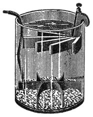
Anyway, you put the copper electrode in the bottom of the jar, and cover it with a layer of copper sulphate crystals (the bluestone) a half inch or a little more deep, fill the jar with water and hang the zinc in it so it is an inch or so below the surface of the water.
Then you short-circuit the thing (connect the copper electrode directly to the zinc) and wait for a couple days until the thing starts to "work" and then you will see the solution separate into a deep blue copper sulfate solution in the bottom part of the liquid and the top part stays clear (zinc sulfate). The liquid solutions will eventually divide so that it is half deep blue and half clear. At this point the cell is at its maximum strength and is ready to be put to work.
The difference in specific gravity of the two solutions is what makes it separate and the cells must remain absolutely still so the solutions don't mix. This difference in specific gravity also gives them their name gravity cell. The shape of the zinc electrode gave them the name crowfoot cell. The blue color of the copper sulphate crystals used to "feed" them with gave them the name bluestone cell.
I've heard that in the old days they put some mineral oil in to float on the water to prevent evaporation and to keep the zinc sulfate from growing crystals on the zinc electrode above the surface of the solution.
These things are messy and require frequent addition of copper sulphate crystals. The copper electrode grows copper deposits and the zinc electrode is slowly eaten away. The cells develop about one volt each, and they need to be used in a circuit that pulls some current all the time in order to keep them working. It was this fact that made this kind of cell ideal for closed-circuit telegraph work.
The copper sulfate solution level reduces as the copper in it is deposited on the copper electrode and the clear zinc solution increases. When the dividing line between the solutions reaches under a couple inches from the copper electrode, it is time to draw off some of the zinc solution (keep it in a dark jug for starting other cells), add copper sulphate crystals to the bottom of the jar, and refill the cell with fresh water to renew it. Short-circuit it for a while to get it going again and then cut it back into the battery string.
This job was why old-time agents and operators hated the gravity cell "locals" in railroad depots so much before there were electric lights…and invariably coerced a student operator to do this messy job if they had one there learning the telegraph business.
Can you imagine the job of keeping a rack of 100 of these things going for a telegraph wire main terminal battery? The cells could be jumpered out one at a time to remove them from the string for maintenance. There wasn't the high current short-circuit danger with these as there was with common lead-acid storage batteries. The gravity cells had a pretty high internal resistance so shorting them out even at maximum strength was not an "electrifying" event.
Les Kerr: Additional information on this topic can be found in The Gravity Battery section of G. M. Dodge's 1921 book The Telegraph Instructor.
Published in Dots & Dashes Vol. 35, No. 2 (Spring 2009)
Question: Using a D cell to power my sounder via the circuit described on the MorseKOB website results in a current of about 200 mA when the sounder is energized. This is considerably more than the 60 mA which I've heard is the normal resting current. Placing a low value resistor in series with the D cell reduces the current, but even with the tensioning spring backed way off it won't sound properly. My conclusion is to obtain the 60 mA resting current a sounder with larger coil resistance is needed. Comments?
—Mike Hardie, North Vancouver, BC
Ed Trump: 200 mA in the sounder loop with only a single 1.5 volt D cell for loop power is about nominal for a 4 ohm local sounder. Measure the coil resistance of the sounder magnet windings and, if the sounder is a nominal 4 ohm type, make sure it is properly adjusted.
First, adjust the magnetic gap between the armature that is mounted on the sounding bar and the ends of the magnet core pieces. Hold the sounder bar down and set the downstop so that there is about two or three thicknesses of ordinary typing paper between the armature and the magnet core pieces. The armature on the sounder bar should not hit the coil magnet cores at all. Make sure there is no mechanical defect in the sounder magnet coil mountings and that they are tightly fastened to the "heel piece" that straps the two cores across the bottom where they mount to the sounder plate so they can't move.
Next check the sounding bar return spring tension. It should be just enough to smartly return the sounder bar to its upstop. Make sure the travel of the sounder bar between the upstop and the downstop is about 1/16 of an inch or a little less. Also make sure the trunnion screws where the sounder bar swings from are properly set so there is no slop, yet the sounder bar moves freely in these trunnions without binding. It must be free to be moved by the magnetic pull on the armature.
If all this is well, the sounder should operate and sound well as the loop is keyed. Make sure you haven't wired a diode across the sounder coil windings; this will make the sounder sluggish. The sounder driver circuit shows the protection diode should be connected across the keyer transistor in a reverse direction between the collector and the emitter.
The normal working current for a 4 ohm sounder is about 250 mA. They were designed to operate with between 1.5 and 3 volts of battery in circuit, no more.
The only time you should be working with 50 or 60 mA in the sounder loop is if you are using a mainline sounder that has coils wound for 100 to 150 ohms. In that case a 1.5 volt D cell won't be sufficient voltage at all. For these mainline type instruments you need around 20 to 24 volts with additional series resistance in the loop to regulate the loop current to about 50 mA. This would be about 360 ohms for a 24 volt supply and a nominal 120 ohm sounder. The resistor should be rated for at least 5 watts. The higher voltage is necessary to overcome the high inductance of the instrument windings. The instruments will work with less, but they won't always sound right.
Chris Hausler: For mainline instruments of 100 to 150 ohms, I find using a 12 volt Radio Shack power brick and putting the instrument in series with a 150 ohm 2 watt carbon resistor works well. These power bricks can serve as a simple and readily available alternative to a higher voltage supply. It's true that larger voltages dropped across larger resistors improve the time constant of the circuit, but I've had no performance problems with the above configuration. In a pinch I’ve even used only 9 volts and very little series resistance successfully.
Les Kerr: In the case of a 4 ohm sounder, remember there's a voltage drop of about 0.7 volts across the Darlington switching transistor that the power supply must overcome, in addition to powering the sounder. If you use a 1.5 volt D cell, for example, that only leaves 0.8 volts to drive the sounder. Enough to work, perhaps, but maybe not as "snappy" as you'd like.
For my 4 ohm sounder, I use a 12 volt power supply in series with a 50 ohm, 10 watt resistor, resulting in a current of about 200 mA. This works well for me.
Published in Dots & Dashes Vol. 34, No. 4 (Fall 2008)
Question: One aspect of the original telegraph system has puzzled me for some time. It appears as though batteries supplied power to the system when no message was being passed, i.e. all the circuit closers on the wire were in the closed position and the various stations were waiting. This seems like a huge waste of batteries. Am I missing something, or was supplying continuous power to the system (and the resulting battery replacement) a requirement?
—Mike Hardie, North Vancouver, BC
Jim Wades: The practice of utilizing a normally closed (NC) system offered a variety of advantages, both economic and technical, a sample of which includes:
As for batteries, the old crowfoot batteries were ideally suited to an NC loop. By the latter part of the 19th century, however, larger telegraph networks utilized power supplied by generators and, later, rectifier units to provide the necessary loop supply current for the various circuits.
For simple telegraph circuits, say between two points, normally open (NO) systems were utilized. Such systems could be powered by dry-cells and the like, and, of course, power consumption was an issue. Perhaps the most common examples are learner's sets and the neighborhood telegraph line! Short telegraph circuits for railroad block operation might be another example.
Ed Trump: There were some very good reasons that the closed circuit system was almost universally used on Morse wire circuits in the USA and Canada. Single wire, ground or earth return circuits were normally used, which had half the resistance of a metallic loop, since the earth return contributed no resistance to the circuit if it was more than a few miles in length. The only circuit resistance was due to the line wire resistance and the resistance in the instrument windings or other equipment in circuit.
With a closed circuit system, all the battery could be located at the ends of the wire circuit, often hundreds of miles apart. All the other stations only had to have a key, relay and local sounder or perhaps only a key and a mainline sounder and a rudimentary switchboard for wire testing and patching.
Mainline battery could be located all at one end of a circuit, and the far end of the wire simply run to earth, but there were some technical reasons for splitting the battery source in two and locating half of it at each end of the circuit. This had to do with improving operation due to line leakage in wet weather and allowed testing for opens and grounds in the circuit from testing offices at the end or intermediate points of the wire.
A typical mainline telegraph wire operated with main battery open-circuit voltages of typically 100 to 160 volts but the line current was nominally only about 50 milliamperes. Thus the actual power consumption was pretty small per wire.
In the early days racks and racks of Daniell cells or gravity (also known as crowfoot or bluestone cells (producing about one volt per cell) would comprise a main line terminal telegraph battery. About 100 cells would be all connected in series for a main battery in a terminal office. Before long, telegraph companies went to steam driven dynamos for DC power and later to AC motor-DC generator sets or AC to DC rectifier type power sources for telegraph purposes.
With an open-circuit system, each station had to supply and maintain its own operating battery to work the circuit, which was an impractical and uneconomical situation for long overland circuits with many stations or offices on them.
Open-circuit systems were more commonly used for block circuits on short stretches of high-traffic railroads, and for practice sets and some private circuits where supplying dry-cell battery at low voltages was not costly. The circuits were also often as not metallic loops which could use low voltage battery supply and ran at much higher current levels than long mainline closed-circuit telegraph wires using low level line currents and higher voltage terminal battery.
Another advantage of a closed-circuit system is that it is always under test. That is, it is a series-connected circuit and any interruption at any point is immediately noticed by all the offices that are on the circuit, because the wire goes open and no communication can be carried out until the circuit is closed again.
In the case of a wire break, the offices along the line could each temporarily connect a ground wire in their switchboards on each side of their office to ascertain in which direction from that office the break was located and start out a lineman to make repairs. The wire would immediately be restored to operation in the opposite direction in this case, and the intermediate ground later removed when the break was repaired and the wire "cut through".
When a wire was not broken but became grounded, thus interrupting through service, a wirechief at a testing point near one end of the wire in question could call up the offices along the circuit in succession on the wire in question or on another adjacent wire and have them each briefly open the faulted wire in their switchboards to ascertain between which two stations the ground fault was located. Then linemen would be dispatched to clear the fault.
Much of the detail of landline telegraphy practices and how it worked has been forgotten, but there are some books available that adequately describe a lot of it. George B. Prescott's History, Theory and Practice of the Electric Telegraph is one such book. It was written around the time of the American Civil war (1866) and is still a good reference on how it all worked. The technology changed but little after that time until the end of the manual telegraph era, circa 1975. Reprints of this book are currently available from book sellers.
Question: I'd like to connect the local telegraph loop at Exporail with the Canadian dialup hub. Unfortunately we don't have a telephone line available for this purpose, but we do have high-speed Internet. Is there any way we can use the Internet to make this connection?
—François Gaudette, Saint-Constant, QC
Les Kerr: What you'll need is (1) a computer at the Exporail site to connect the telegraph loop to one of the MorseKOB wires, (2) a second computer at some other location to link that MorseKOB wire to the Canadian hub, and (3) an operating agreement with the MorseKOB and dialup hub wire chiefs to set up the link between the two systems.
1. MorseKOB loop interface
Connecting a key (straight key or bug) to a computer running the KOB program is very simple. All you need is a pair of wires from the key to a serial port on the computer. If your computer doesn't have a serial port, you can use a USB-to-serial adapter instead. Details on how to do this are in the MorseKOB Tutorial.
Adding a sounder is not much harder, but you'll need to build an interface circuit such as the one described in the MorseKOB Tutorial. It only requires a few inexpensive parts.
To tie into an existing telegraph loop, like you have at Exporail, is a bit trickier. For this you'll need a MorseKOB loop interface. Assembling this circuit requires more skill than the simple sounder driver, but once you get it working it does a fine job.
2. MorseKOB dialup interface
Anyone with a dialup modem and a computer running the KOB program can provide dialup access to the MorseKOB network. Here's what you need:
The MorseKOB modem cable is used to connect the modem to the computer, but it's not the same as a standard, off-the-shelf 9 pin to 25 pin modem cable. It needs to be wired with the following pin connections:
| DB9 female |
DB25 male |
|---|---|
| 7 | 2 |
| 6 | 3 |
| 5 | 7 |
Since the modem is connected to the computer's serial port you won't be able to use an external key or sounder at the same time, but you'll still be able to send using the computer's keyboard and hear incoming Morse over the speakers.
3. MorseKOB and dialup hub coordination
With the equipment described above, you can enable a single dialup Morse user to access the MorseKOB network whenever you like. Technically, moreover, nothing prevents you from using your modem to call one of the dialup hubs, which then connects all the users of that hub to the MorseKOB wire. If this is done in an unplanned manner, however, disruption to the system is possible and other users could be impacted.
Therefore, it's important to coordinate in advance with the wire chiefs of the MorseKOB system (Les Kerr) and the dialup hub (Tom Hamblin in the case of the Canadian hub, Jim Wades for the U.S. hub). Dates and times of operation, the MorseKOB wire number to be used, and other requirements can be agreed upon to ensure smooth operation for all concerned.
Internet link between the Exporail site and the dialup hub
The block diagram shows the main components of the system, with dashed lines representing connections made over the Internet. XO is the telegraph office at Exporail, and BA is Barrington Station, located ¾ mile away. The offices are equipped with 120 ohm mainline sounders and the loop supply voltage is 120 VDC. There are actually two separate circuits between XO and BA, but for simplicity only one is shown in the diagram.
Question: I would like to set up a working Morse display for the Train Depot Museum in Kingsville, TX. The train depot was built in 1904 and I'd like the display to reflect telegraphy of that age. The original telegraph system probably required the use of batteries since the town of Kingsville was established in 1904 as a railroad town and at that time the community was not yet on the power grid.
The train line through Kingsville runs from Robstown to Brownsville, a distance of 142 miles. How many batteries would be required to transmit messages over 142 miles? How many volts? If a message was sent from Robstown to Brownsville would it travel the entire distance or would it have to be copied by a telegrapher and resent somewhere in between the two towns?
The museum has a number of mainline sounders and keys, and also a Western Union 4-C relay. I'm setting up a 4 foot board with a key and mainline sounder, and I'm making little telegraph poles to hold the wires. I want to incorporate the relay as well, but I'm not totally sure what its function was. Can you give me a description of its use?
I plan on using a 9 volt battery to power the set up. How would the relay be connected? I'd like to simulate a battery from the 1904 era. Would a crowfoot battery be appropriate?
—Patricia Allison, Kingsville, TX
Ed Trump: Telegraph wires were powered by direct current (DC) and in the 1904 era were powered by large main batteries in the telegraph offices at each end of the wire. One single iron wire was used for the line between the offices, insulated on the poles with the common type glass insulators. Earth was used for the return current path. The main line batteries at each end of the line were made up of large numbers of one volt cells wired in series to provide a total voltage of about 100 volts.
With 100 volts of terminal battery at each end of the line, the DC current in the telegraph main line wire would be about 50 to 60 milliamperes for a line around 150 to 200 miles long constructed of galvanized No. 8 iron wire, which was pretty much the standard for line construction from the 1860s Civil War period to the end of the telegraph era in the 1970s — over 100 years.
A telegraph line would easily work over the distance from Robstown to Brownsville. That is, Robstown could easily send direct to Brownsville without any relaying done at any intermediate point.
Since a telegraph wire is a series DC circuit, any office connected in the line could send and all the other offices in the circuit would be able to receive the message. The telegraph keys had a circuit closing lever on the right side, and when the key was not actually being used to send with, this circuit closer had to be kept closed to keep the line circuit closed, else no communication could be done. An office wishing to call another office would open the circuit closer on his key, then work the key to send the Morse code call letters of the office it wished to communicate with, and then close his key circuit closer to wait for the distant office to answer.
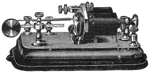
Morse relay
The Morse relay was an instrument that was used in nearly all telegraph offices circa 1904. Its purpose was to repeat the Morse signals from the relatively small current in the main line wire into the local loop circuit that was connected to the contacts of the relay and operate the local sounder with a clear and distinct signal no matter how weak the signals were in the line circuit.
The electromagnet coils in the relay were connected in series into the main line circuit from the switchboard where the main line wire was brought into the office from the towns in either direction. The contacts on the mainline relay were connected so they could make and break the circuit to the local sounder magnet windings. The local sounder circuit was powered by two crowfoot cells that provided about one volt each. The crowfoot cells were wired in series with the local sounder coils and the relay contacts. Battery type local sounders were wound to a resistance of about 4 ohms and used 3 volts for battery. Local circuit current was about 250 milliamperes with the 4 ohm sounders.
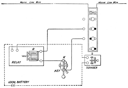
Telegraph office with relay and local sounder
Each telegraph office on the same line was equipped with a switchboard, a key, a main line Morse relay, a local sounder, and a local battery. The main line wire came into the switchboard from each direction, and was then connected to the instruments on the operator's table. This put the relay magnets and the key in series with the line circuit. The contacts on the relay were connected in series with the local sounder and the local battery, which normally consisted of two crowfoot cells in series.
The switchboard had a ground wire available on it and means of opening the line circuit on each side of the instruments in the office and attaching the ground wire in place of the line wire. This was provided so that if the line wire were to be broken down or burned down by lightning in one direction or the other, the operator could temporarily connect the ground wire and thus restore communications with the distant offices in the opposite direction from the break in the line, using the current provided by the terminal battery at that distant end of the line.
Of course if more than one wire ran along the pole line, the switchboard provided the means of not only connecting in the relays and keys in the office assigned to the other wires, but provided a means of testing and crosspatching the line wire circuits if it became necessary in case of line troubles.
To set up a simulated telegraph circuit, ideally
you
would need a Morse relay, a key, and a local sounder at each
end of the display on your board. You would then equip each
end of the line with a local circuit connected to the relay
contacts and two cells of (simulated) crowfoot battery for
local circuit power and the local sounder.
If you have only one relay, you can substitute a main line sounder at the other end and wire it in series with the key and not use a relay and local sounder. This was common practice in offices where maintenance of a local circuit and its batteries was not desired.
If you don't have any local sounders, you may use a mainline sounder in place of a local sounder in the relay's local circuit. You will have to use about 6 volts DC for the local circuit instead of 3 volts as the 120 ohm main line sounder needs more battery to work.
The main line circuit would then use one single wire conductor between the "offices" on your small poles. You would have to hide a wire under the board to simulate the "earth" return connection.
For a simple display like this, you don't need to provide main line battery at each end. Putting it all at one end will suffice.
To power the main line circuit you will need about 12 volts DC to power it properly. Each relay or main line instrument in the main line circuit will be about 120 ohms, two instruments in series will make the total circuit resistance about 240 ohms. Ohm's law says that the current times the resistance will equal the voltage needed in the circuit. (Voltage E in volts = current I in amperes x resistance R in ohms.) In this case you will want about 60 milliamperes or 0.060 amperes to properly operate the telegraph instruments, and you have about 240 ohms resistance in the circuit neglecting negligible resistance in the connecting wiring. So 0.060 x 240 = 14.4 volts will be needed for power in the main line circuit. You should be able to find a small "wall wart" DC power supply that will provide 12-14 volts DC at 100 mA or so to power your exhibit with.
For the local circuit on the relay, use six volts DC to power the 120 ohm main line sounder if one is used as a local sounder.
We do ask one thing…VERY IMPORTANT…If you display a copy
of the MORSE CODE with your display, PLEASE make sure you
display the AMERICAN MORSE Code which was the code used on
telegraph wires in the U.S. and Canada, and not the
"International" Morse code as is used on radio
circuits by radio amateurs.
Question: Conventional telephone twisted pair builds up capacitance rapidly, necessitating addition of load coils or other equalizing methods to pass the higher audio frequencies. In a single wire elevated above ground as in telegraph circuits it would seem line inductance would build up on very long runs, capacitance not building up as it does on twisted pair so rapidly. What effect does it actually have? It seems inductance would make the sounder sound "soft", not a sharp snap.
—D. E. Wiggins, Valparaiso, IN
Ed Trump: Single wire earth-return DC telegraph circuits suffer very little from line inductance. The lumped inductance of the magnet coil windings in the series connected telegraph instruments far outweighs the contribution of distributed line conductor inductance, and is mostly responsible for line current rise-time delay.
Very long circuits will have distributed capacitive reactance with earth that somewhat counteracts the inductive properties in opening and closing the circuit, but the combined effect is fairly negligible on even long open wire single conductor circuits.
As long as the open-circuit terminal voltage applied to the circuit is sufficient to reduce the line current rise time when the circuit is opened and closed, the distributed inductive and capacitive properties of the line wire itself have little effect on circuit operation. This is one reason main line terminal battery voltages were kept at a fairly high value, usually higher than 80 volts, and typically around 130 to 160 volts at each end of very long circuits. Polar circuits, where the operating battery is reversed in polarity rather than simply turned on and off on the circuit, are affected by line conductor inductance and capacitance even less.
DC telegraph operation over cable circuits, where the conductors are in close proximity with other cable conductors and the cable sheath, is much more affected by the higher distributed capacitance in the cable. Operation is much different than that of open wire line on poles in regard to both keying speeds and distance that can be run without regenerative repeaters.
Published in Dots & Dashes Vol. 35, No. 1 (Winter 2008-09)
Question: I have just started to get into signaling and Morse code and a friend found me two Signal Corps telegraph sets at a garage sale. These are U.S. Army TG-5-B sets complete with headphones, buzzer and key. They work, but I know absolutely nothing about hooking them up. According to the wiring diagram's instructions I think I need a 45 volt power supply.
Where can I get the instruction manual for this type of telegraph set and do I need a 45 volt supply or is that amped up from the battery box in the unit?
—Mark Horn, Kelso, WA
Les Kerr: You're in luck! The instruction manual for your telegraph set can be downloaded from www.royalsignals.org.uk. This marvelous site has manuals for a wide variety of military equipment (most famously the No.19 wireless set, which I used as my first ham radio station many years ago). The manual you need is TM 11-351, which covers the TG-5 and TG-5-A telegraph set, and you also need the July 1943 supplement for the TG-5-B model.

TG-5-B Field telegraph set (click to enlarge)
You won't need a 45 volt supply to operate your telegraph set, or even the 22.5 volt line battery that it originally came with. The TG-5-B has a 4,400 ohm relay that can be adjusted for line currents as low as 0.2 mA, so a 6 volt screw-top lantern battery (NEDA 915 or equivalent) should work nicely with your pair of sets. Or, instead of a lantern battery, you could make yourself a battery pack that accepts four D cells. You'll need a separate line battery for each set, and also a pair of D cells per set for the local battery.
The line battery is connected to the binding posts marked + and -22. The only other thing you'll need is a pair of wires between your two sets connecting binding posts L1 and L2. The manual gives detailed instructions on how to test the installation and adjust the relay spring tension for proper operation.
Published in Dots & Dashes Vol. 35, No. 1 (Winter 2008-09)
Question: I'm a ham radio operator, NYØO, and I'd like to know if there's some kind of course available for the landline Morse code. I like the old western TV shows and you hear the landline Morse on occasion, but I only know the international code. I'd like to be able to learn a little click and clack Morse. Are there any online courses available?
—Ben Johnson, Mount Union, IA
Les Kerr: The "KOB Morse Course" was designed exactly with someone like you in mind: the CW operator who wants to make the transition to American Morse with a sounder. The course works in conjunction with the MorseKOB program, which can be downloaded from morsekob.org. Click on the "KOB Morse Course" link on the MorseKOB home page to download the course material.
The best thing about the KOB program is that you can also use it to hear live operators sending landline Morse over the Internet. In fact, Sid Vaughn, one of the pioneers of Internet Morse, lives not far from you in Cedar Rapids. Sid helped shape the KOB program's design to make it more useful for CW operators like yourself.
Question: I noticed in The Telegraph Instructor by G. M. Dodge (7th edition, 1921) the table for the Continental or International Code gives strange codes for some of the punctuation marks. For example, the code given for the period ( · · · · · · ) is neither American Morse nor standard International Morse/Continental Code. What’s going on here?
—Ernest Unrau, Morden, MB
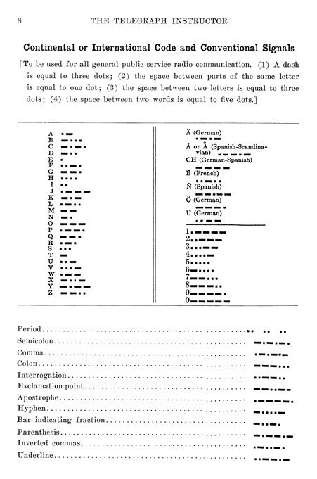
A page from the 1921 edition of The Telegraph
Instructor,
by G. M. Dodge. Note the unusual codes given for
the period, comma, and exclamation point.
Les Kerr: This was the toughest question sent to the Wire Chief so far, and it very nearly stumped our panel of experts. It was tempting to dismiss these weird codes as mistakes by Dodge or typos introduced by the book’s publisher.
Further investigation revealed there’s more to the story, however. The January, 1939, issue of QST advises hams to "use new punctuation symbols." The QST article goes on to provide the following explanation:
The International Telegraph Regulations, as revised at Cairo, 1938, made certain changes in the International Morse Code as follows:
(a) The former period sign · · · · · · was changed to · – · – · –
(b) The comma sign shall be – – · · – –
Therefore, at the time Dodge wrote his book, the codes he gave were correct.
Digging even deeper, I discovered that the original Continental/International code for the period, standardized in the mid-1800s, was a string of six dots ( · · · · · · ). The extra spacing wasn’t introduced until around 1900.
It’s interesting to speculate why the original code was six dots, why it was later broken into three groups of two dots, and how it finally transitioned to the code we have today. Perhaps the string of six dots was too easily confused with the number 5 (five dots) or the error signal (eight dots). And the underlying rhythm of the modern code for period, didahdidahdidah, is exactly the same as for the spaced code didit didit didit.
The most intriguing document I came across during my search for information was a 166-page report written in 1869 by Samuel Morse himself. Morse was a U.S. commissioner to the 1867 Paris Universal Exposition, and his report is a commentary on what he observed there.
Chapter 3 of Morse’s report addresses the topic of codes, and it provides some fascinating insight into his thinking on the subject. Morse apparently had second thoughts about the wisdom of the spaced letters in his original code, and he generally supported the European efforts to update the code. He did not agree with their choice of codes for punctuation, however. His own recommendation for the period, in fact, was a single dot—the same as the letter E!
Published in Dots & Dashes Vol. 35, No. 3 (Summer 2009)
Question: What lubricant should be used for keys, relays, sounders, and other telegraph items?
—Garry Tidler, Sharpsville, IN
Chris Hausler: I'd suggest a cleaning of the "bearing surfaces". I've seen cases where rust and or grime will interfere with the pivoting of a key or sounder at the trunnions and all that is needed is a good cleaning and maybe a little polishing and rust removal with emery cloth or some similar fine abrasive if necessary (unless it's real bad and more aggressive procedures are needed). I just usually use some paper towel and that's abrasive enough. I suppose a little graphite wouldn't hurt for lubrication if believed to be necessary, but I wouldn't use any oil of any kind.
Jim Wades: I agree with Chris's assessment. I've never lubricated a telegraph instrument. However, if I were to lubricate a bearing surface on a telegraph instrument, I would probably use Rem Oil, which is readily available at gun stores or any sporting goods store that carries firearms. I would also use it sparingly.
Derek Cohn: For pivots, I have to agree with Chris. I think in very few situations have I had to add a lubricant. Usually, if a pivot isn't working properly, it's dirty and/or rusted. I clean off the dirt and/or remove the rust and the bearing seems to work fine. I sometimes smear 3-in-1 oil onto the cleaned surface but that's to retard further rusting. I don't see any harm in adding a little bit of oil to the pivot points, though some people might point out that it's an insulator and many of the pivots are in the loop path (which is why Vibroplex adds the copper pigtail to their bugs with jeweled bearings).
For moving threaded parts, such as dot contact screws, spring adjustment screws, etc., I use 3-in-1 mostly because of the handy can dispenser. The teletype guys who I pal around with hate 3-in-1 oil for their machines (but those are high wear, high temperature, high contaminant applications) and say that Teletype corporation recommended 20w non-detergent motor oil. I was able to find some at our local "good" hardware store (not the big-box type) and that's probably what I should use for lubing my keys.
In summary, I think most stuck pivots are the result of crud/rust that can be cleaned off to make the travel more smooth. Add any oil you like afterwards. To improve the travel of threaded components, I use 3-in-1.
Question: How was a railroad telegraph wired to the line? I've never been able to find drawings or photos which show the actual, physical methods of tapping the overhead wire and bringing the wiring into the station building ---- including the means of providing for lightning protection and physical location of the hardware.
—John Schneider, Roswell, GA
Ed Trump: A telegraph circuit is a series circuit; that is, all stations are connected in series with one another. Any station opens the circuit and sends, all the other stations connected on that wire receive what is sent.
The telegraph line wire is physically broken on a designated pole near the station by means of what is called a break iron. This is a short iron bar about eight inches long, an inch and a quarter wide, and about half an inch thick. On the ends of this bar are two metal insulator pins, with wood cobs and standard telegraph insulators screwed thereon.
The break iron is mounted on the top of the crossarm so that the two insulators are in line with the wire to be cut in. The wire is cut and deadended on the two insulators. The wire is pulled around the insulator and twisted on itself twice, then three buttons are wrapped around the main wire, and a short "pigtail" is left pointing down. This provides a break point in the telegraph circuit in that wire, and preserves the strength of the pole line construction.
Early construction then ran two wires from the break iron in a slack span down to some insulators fastened to a crossarm fixture on the station wall to bring both directions of the circuit to the building. Smaller gauge copper wires then attached to these drop wires, and ran inside the building through insulating bushings to the location of the switchboard.
Later construction utilized a cable box located on the top of the station's cable pole. Smaller gauge insulated copper bridle wires were connected to each pigtail on each side of the break irons and then routed up into the cable box through insulating bushings where they were connected into the cable that ran down the pole and into the station building to the switchboard location.
Early switchboards were generally of the crossbar type with the line connections for each circuit entering the building connected at the top of a pair of vertical brass straps mounted on a hardwood backing that was in turn mounted on the wall, or in heavy lightning districts, mounted on some iron straps that stood it out away from the wall eight inches or so. This was to prevent lightning from setting the building afire in case of direct lightning strikes—hopefully the resulting fire in the switchboard could be extinguished before it set the wall afire. Sheets of tin were usually fastened to the wall behind such switchboard installations to provide further fire protection.
There was a pair of vertical straps for each wire terminating in the switchboard, thus presenting both directions ("east" and "west", or "north" and "south") of the line circuit for making connections. The office instruments, telegraph relay and key, were connected via crosswise copper straps on the back side of the wood switchboard frame that connected with brass buttons or discs on the front of the board located between each vertical pair of line straps. Holes were arranged between the vertical bars and the rows of horizontal discs so that little brass pegs with insulated knobs could be pushed in to make connections between the discs and vertical straps. Any vertical bar could be connected with any horizontal disc, making it possible to connect a set of instruments, open, ground and crosspatch to any wire in the switchboard.
Each wire that had instruments assigned to it had a pair of pegs in the switchboard connecting the key and relay to the east and west (or north and south) directions of the circuit. The key and relay for each wire were connected in series with one another at the telegraph desk or table. In this manner, the telegraph circuit made a complete loop from the "east" line into the station, to the switchboard, through the key, relay back through the switchboard and back out to the "west" line.
When the telegraph office was unattended, Company rules usually dictated that the instruments on all wires in the office were to be cut out or disconnected from the line circuits at the switchboard. This was easily accomplished by moving one of the pegs in the board.
A typical railroad way office would have three sets of instruments, a key and relay, on the telegraph table. One was typically for the Railroad Dispatcher's wire, one was for the Railroad Company message wire, and a third set was for the Western Union way wire. There were possibly other "thru" wires brought into the switchboard for testing purposes only, that did not have instruments assigned to them. These wires were simply cut through at the switchboard and not disturbed except on specific direction of the distant wire chief in case of testing for troubles.
Lightning protection in the early installations was rudimentary and consisted of only a horizontal brass strap that was positioned across all the vertical line straps on the front of the switchboard with a small air gap of a couple thirty-seconds of an inch between it and the line straps. The horizontal bar was permanently connected to the station's ground plate buried in the earth.
Near lightning strikes on the line would cause arcing between the ground strap and the line straps on the switchboards, and the ground strap would have to be taken off occasionally and carefully dressed with a file to remove pitting damage due to this arcing. This arrangement normally provided sufficient protection to all but direct lightning strikes on the line nearby. Nothing much protected the office from those, and lightning damage to instruments and switchboards was not uncommon.
Additional holes between the line straps and the ground bar on the switchboard allowed connection pegs to be inserted to ground any wire "east" or "west". In case of a line failing open this was done to determine in which direction the trouble was from the station.
Later improvements in switchboard design after the turn of the 20th century provided line and instrument fuses and better lightning arrestor devices, and provided line and patching jacks for each line and instrument connection so that wire patching and testing was made easier and safer for the operators.
Edited by Les
Kerr
Revised 2010-04-18
MTC Home Page